3S Quadcopter
Introduction
This is a planning page for a quadcopter using 3S batteries, more exactly something around 2100mAh. That's the same battery Align T-Rex 450SE V2 uses and seems to be somewhat commonly used in quadcopters too. The frame could be similar or even the same as with the 8" prop 2S Quadcopter.
For controller software, I've opted to use the Arduino based MultiWiiCopter instead of Arducopter. The reasoning is that ArduCopter seems to be more aiming to be an UAV controller with GPS and flight planning software. Based on forum talks, the Arducopter developers mentioned that flying the software without GPS is something less tested and less used, which suggests it isn't the best option for a more stunt like quadcopter. The code base is now shared with ArduPilot and that adds extra bloat to the code. MultiWiiCopter on the other hand supports a wider range of sensors and setups. The smaller code base should also make it easier to investigate problems if such arise.
Size
The size of a quadcopter is mostly made of the length of motor arms and used props. Fancy camera mounts or landing gears can make the thing taller but that isn't usually an issue from a handling point of view. Since I plan to use this quadcopter for flying during the winter season (=indoor) and also as a stunt, a smaller size than the Arducopter like DIY quadcopter was the target. Suitable motors dictate the prop size and that's how I ended up with 8" props. Those are proved to work well and are easily available, even in different colors (going with black & orange).
With 8" props, the smallest possible motor to motor distance is around 32 cm. Anything smaller than that will cause props to hit each other. However, the minimum distance isn't very optimal since in such setup the air around the props will constantly be disturbed and that's likely to reduce performance or stability. Originally, I was planning on using a 34 cm motor to motor distance but noticed that with such distance, it wouldn't be possible to fit two strips of led lights between the motor mount and the baseplate. The led strips can be cut to pieces of 5 cm and I ended up being at least 1 cm short for having two strips. That resulted in the use of longer arms (20 cm) providing space for more leds and resulting in a motor to motor distance of 37 cm. The arms flyduino.com is selling are 25 cm so this build will result in a slightly smaller quadcopter. It remains to be seen how this affects the PID settings since the default settings appear to work fine at least with the 25 cm arms.
Note that 1 cm of 1x1 cm square tube with 1 mm wall weights about 1 gram so the length of used arms will directly affect the weight of the quadcopter. By increasing the length of motor arms by 1 cm, you end up increasing the weight of the quadcopter by 4 grams.
Motor options
| motor | weight (g) | size (mm) | rpm/v | current | shaft (mm) | prop | battery |
|---|---|---|---|---|---|---|---|
| Keda A20-50S | 29 | 22x28 | 1088 | 2-6A / 8A | 3.17 | 9x3.8 | 2-3S |
| Suppo 2208-17 | 36 | 28x27 | 1100 | max 8A | 3.2 | 3S |
Keda seem to be the best options currently. Suppo is heavier and its availability doesn't seem to be that good either.
Weight and cost
The weights are currently only rought approximations and the prices have been somewhat rounded upwards.
| item | weight (g) | cost (€) | note |
|---|---|---|---|
| 4 x motor @ 36 g | 144 | 46 | Keda A20-50S with prop adapter |
| 4 x 10A ESC @ 10 g | 40 | 37 | Hobbywing Flyfun 10A, long wires could use some cutting |
| 4 x 1x1x20 cm square tube @ ~20 g | 80 | 2 | 20 cm arms will give a motor to motor distance of about 37 cm |
| 4 x 8" prop @ 5 g | 20 | 4 | 8x4.5 from flyduino.com |
| FrSky TFR4 receiver | 7 | 22 | with ppm so less wires will be needed |
| Turnigy 2200 mAh 3S | 200 | or something similar, the weight range seems to be the same | |
| Arduino Pro Mini 328 | 2 | 15 | 5V/16MHz |
| FreeIMU 0.3.5 BMP | 3 | 79 | |
| Warthox MWC shield v5.0 | 14 | 8 | |
| Baseplates | 42 | 14 | |
| Wires and screws | 20 | 5 | just a guess |
| Coverplate | 7 | 3 | optional, provides some shielding for the electronics |
| Led stripes | 4 | 10 | optional, for better visibility |
| = | 553 | 245 | |
Cost reduction possibilities
- IMU
- replace FreeIMU with IMU 6DOF IMU from drotek.fr (35€, save ~44€)
- replace FreeIMU with sensors from Wii Motion Plus (10-15€, save ~64-69€)
- Frame
- replace Flyduino baseplates with DIY alternatives (save ~10€)
- build without coverplate
- build without leds (save ~10e)
- A minimal setup costs probably around 150€
Item sources
Flight time estimation
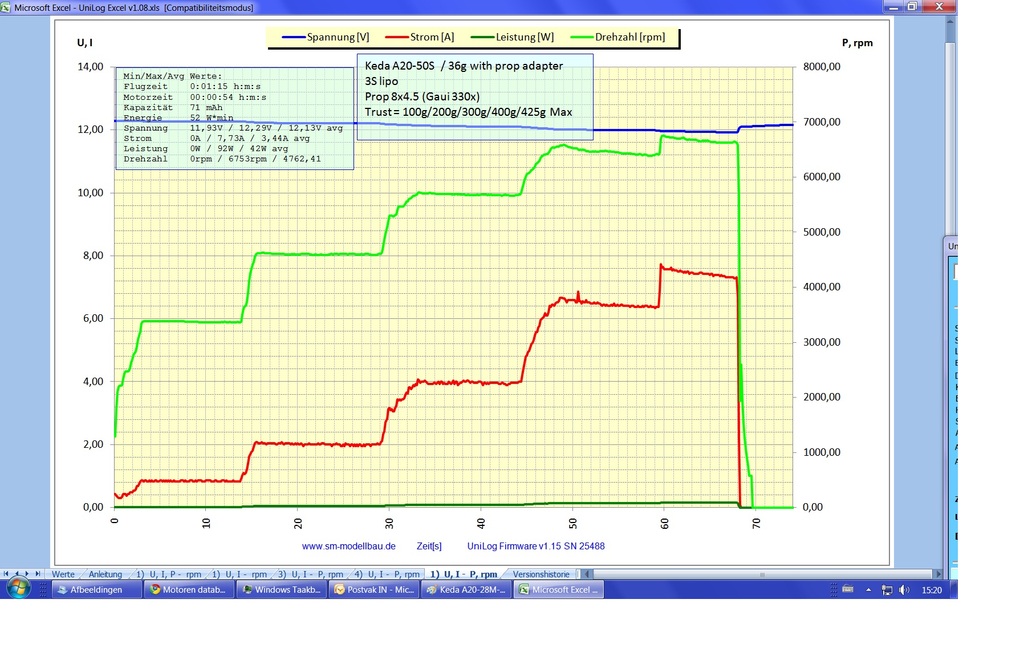
Keda A20-50S, 3S with 8x4.5 prop.
Rcgroups data from: http://www.rcgroups.com/forums/showthread.php?t=1388583 (image cached here).
Own test: http://www.youtube.com/watch?v=HzIiaAJqSuo
| thrust | current | ||
|---|---|---|---|
| rcgroups | own test | ||
| 50 g | 0.3A | 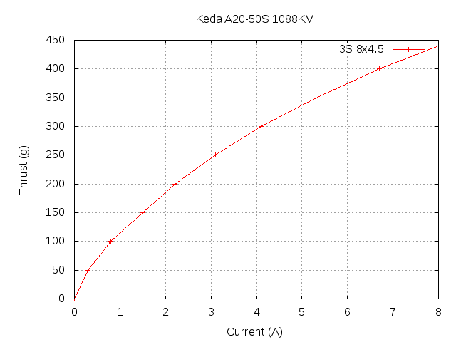 |
|
| 100 g | 0.4A | 0.8A | |
| 150 g | 1.5A | ||
| 200 g | 2.0A | 2.2A | |
| 250 g | 3.1A | ||
| 300 g | 4.0A | 4.1A | |
| 350 g | 5.3A | ||
| 400 g | 6.4A | 6.7A | |
| 425 g | 7.6A | ||
| 440 g | 8.0A | ||
With the planned weight, the quadcopter should be able to hover with about 150 g thrust from each motor (4 x 150 g = 600 g). Based on earlier tests, the current of one motor for 150 g thrust is around 1.5A. With that assumption, 4 x 1.5A = 6A would be the total current required for hovering. For some reason that ends up being the same value as with the 2S Quadcopter plan.
| capacity | calculation | time |
|---|---|---|
| 2.2A | 2.2A / (6A / 60min.) | 22 min. |
| 1.8A | 1.8A / (6A / 60min.) | 18 min. |
| 1.4A | 1.4A / (6A / 60min.) | 14 min. |
If the battery isn't totally drained (like it shouldn't), a 2200 mAh battery can be expected to have something between 1400-1800 mAh of usable capacity. That would be a very fair hovering time of 14-18 minutes which probably translates into a flight time of 10-12 minutes depending on flight style. This also explains why this sort of setup is also flown with 1000-1500 mAh batteries since such will still provide enough time to fly.
Interestingly, as a comparison, the Align T-Rex 450SE V2 gets about 6-7 minutes flight times with a 2200 mAh battery. Probably less with a more aggressive flying style than I have.
Building it
Instead of writing a build log (hah, blog) and possible end up giving instructions to something that doesn't work, I decided to first build this quadcopter, do test flights and only after that publish the documentation if everything worked as expected. The good news is, the end result flies well and looks nice. Videos of the maiden flight can be viewed from the following links:
The first video shows the very first lift off and minor trimming needed to get the quad stay in level in acrobatic mode (=only gyros active). The second video demonstrates how the LEDs light up the environment in darkness. The later video was recorder within few minutes after the first one using the same battery.
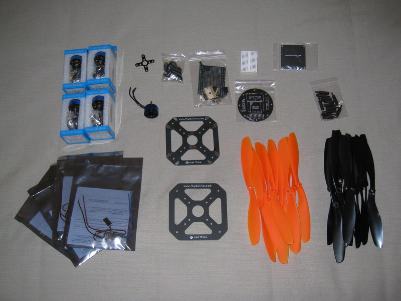
Back to the beginning. It all starts with a mixed selection of parts. The parts are the same as in the weight and cost section table, including optional parts. Some parts aren't shown in the image above. Note, that there's also few spare parts visible, including one extra motor, esc and several propellers.
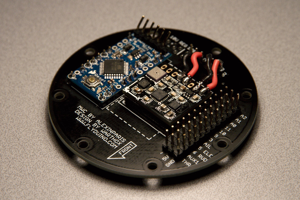
The brain
Assembly
The assembly is fairly simple since there aren't that many parts:
- solder upward pointing pin header to Arduino mini (this is where the FTDI adapter will be connected for programming)
- solder pin header for Arduino (upper center in the image), connectors and IMU to the shield
- solder Arduino to pin header in the shield (or use female pin header if you want to be able to remove the Arduino easily some day)
- align the IMU with the shield (make sure the orientation of the IMU is correct!) and tape it with double sided foam tape
- use gyro tape, "Biltema mattoteippi" or similar
- stack the tape in order to get a layer about 4-5 mm thick
- solder the IMU to the shield with flexible wiring, using a pin header in the shield may help
- SCL - SCL
- SDA - SDA
- GND - GND
- VIN - 5V
Few additional notes:
- the image above shows the pin header in the Arduino bent to a slight angle but I later noticed that the direction will be obscured by a spacer so don't bend it
- make the wires between the IMU and the shield bend in S form to lessen the conductivity of vibrations
- use smaller wire than in the image if available
Software setup
Uploading and configuring the software requires a computer with an USB or serial port, Java support, an FTDI <> USB or FTDI <> serial adapter and a 5V battery or power source for powering the IMU. Yes, that's right. The IMU isn't getting powered via the USB connection.
Setup in Arduino
- get and install Arduino 0022 (or later) from arduino.cc (the file is named arduino-0022.zip)
- note that you'll need to have also Java installed
- Arduino 1.0 has been released and seems to contain changes that might break compatibility so it might not hurt to use version 0022 or 0023 instead
- check that your FTDI<>USB adapter is detected by the operating system but don't connect it yet to the Arduino
- I'm using FTDI Breakout Reloaded from Watterott
- make sure the pin order is the same as in the Arduino before connecting
- go to code.google.com/p/multiwii/ → Downloads and get either the latest release or 1.8 patch 2 (shown here)
- extract the "MultiWii_1_8_patch2" directory to the installed Arduino Sketches directory
- after starting the Arduino SDK, MultiWii should be visible in the load sketches menu
- open the config.h and configure it based on your needs (changes compared to 1.8p2 defaults for FreeIMU v0.3.5_BMP and my setup)
- #define MINTHROTTLE 1180
- //#define INTERNAL_I2C_PULLUPS
- //#define FAILSAFE
- #define FREEIMUv035_BMP
- #define ITG3200_LPF_98HZ
- #define SERIAL_SUM_PPM ... // Futaba
- //#define VBAT
- run Verify to check for errors
- select the correct Arduino board: Tools → Board → Arduino Pro Mini (5V, 16 MHz) w/ ATmega 328
- connect the FTDI adapter and select the correct serial port
- upload and watch the leds blink

Setup in MultiWii conf
- power up the IMU with a 5V power source
- also the receiver needs to be connected in order to get all features visible
- 5V power source ↔ receiver with ppm ↔ MWC shield throttle channel
- if ppm isn't available then all channels need to be connected separately
- locate the MultiWiiConf directory ("MultiWiiConf_1_8_patch2") that came with package from code.google.com and start the configuration program
- 32 bit Java needs to be installed for the configuration program to run correctly in Linux
- "MultiWiiConf_1_8_patch2" script may require few additions
- export JAVA_HOME=”/usr/lib/jvm/ia32-java-6-sun
- export PATH=“$JAVA_HOME/bin:$PATH”
- select the correct USB or serial port
- press "START", wait a few seconds and press "READ"
- if this is the first start and sensor data makes no sense then press "CALIB_ACC"
- wait several seconds followed by "WRITE"
- reset the board and the connection, this should fix the readings
Goals of this setup
- the sensor data should now be visible
- if a receiver is connected then the channel data should also be visible and react correct to stick input
- check that the sensors react correctly to tiltin the shield
Transmitter setup
A Futaba 8FG is used in this example but the same or similar settings should be available in most other transmitters.
Channel setup
- with the help of MultiWii conf, check that all connected channels are visible and move to the correct direction
- I needed to reverse throttle AND ele (pitch)
- set the travel limits for all channels to 120% (Futaba)
- the goal is to have all channels send values as close a possible to the 1000 - 2000 range (low - high)
- check that the middle point for all channels is 1500
- for Futaba it's 1518 by default for some reason, fix it by setting a sub-trim of -29 to all channels
Now all channels should show 1500 when the stick is in the middle position, 1000 in low and 2000 in high. There could be a variations of 1-5 but that shouldn't matter. Notice how moving the stick to the center from a different direction can result in a slightly different value, i.e. 1497 or 1501 instead of the previous 1500. That doesn't matter in flight.
Optional mode switch setup for 8FG
The MultiWii software supports using two channels (aux1 and aux2) for controlling modes (see the picture from the previous section). I wanted to use once channel (aux2) for arming the motors in order to have an arming switch instead of "left stick to lower right arms". However, I also wanted to have a separate switch for enabling and disabling the magnetometer.
This would result in the following setup:
- switch SA arms motors only in high position
- switch SF turns mag on/off
- switch SE is the flight mode switch
- low: acrobatic mode (=gyro only)
- mid: stable mode (=gyro+acc)
- high: stable mode with barometer
In MultiWii conf:
- aux1 low: all off
- aux1 mid: level on
- aux1 high: level on, baro on
- aux2 low: all off
- aux2 mid: arm on
- aux2 high: arm on, mag on
Channel mixing will result in aux2 being high only when switch SA is high, no matter the position of other switches:
- Mix 1: SF → Aux2, act on, link off
- -80 - -50
- offset: x: +50 y: -100
- Mix 2: SF → Aux2, act on SA (only high position), link off
- -100 - +100
- offset: x: +0 y: -25
The frame
Assembly
Building the frame starts with cutting four 20 cm pieces of 1 x 1 cm square aluminium tube. Round the sharp edges once cut. The 20 cm length is calculated for a 8" propeller but up to 10" will fit. Accuracy is important while working with the motor arms. Any deviation may result in arms that aren't straight which in turn places the motor in asymmetrical position. This will cause correction need during software tuning and may some times even result in a quadcopter that isn't possible to tune into flying well in all conditions. However, don't worry if the lenghts of the arms don't come exactly identical. Getting the lengths withing few millimeters is enought. It's more important that the holes have equal distances in each arm and are correctly aligned.


The table below shows the distances for the 3 mm mounting holes that are needed for attaching the baseplates (first 3) and the motors (last 2). All measurements are made from the beginning of the arm so slight deviations in arm lenghts will not matter as long as all arms are at least 20 cm in lenght. One 6-8 mm hole may need to be drilled between the two motor mount holes if the motor shaft doesn't end at the bottom of the motor. At least the Keda motors required this additional hole since I didn't want to cut the shaft.
| 3 mm mounting hole distances | |||||
|---|---|---|---|---|---|
| 10,8 mm | 21 mm | 40,5 mm | --- | 160 mm | 192.7 mm |
Note that I'm using the cross shaped mounting piece for the motors. The reason is that the mounting holes in that piece are symmetrical resulting in free orientation of the motor. The other mounting holes that are directly in the motor aren't in a symmetrical pattern and the orientation seems to be random. Because I want to have the motor wiring point to a specific direction (=away from the front), using the direct mounting holes isn't an option. The cross shaped mounting piece appears to be somewhat standard since my other motors also have exactly the same spacing. Additional, it may provide a little bit of extra protection for the motor bell. Any hits from the sides will first make contact with the mount instead of the motor.

| Screw and nut list | ||
|---|---|---|
| 4 | 20 mm M3 metal screw | inner baseplate |
| 4 | 40 mm M3 metal screw | outer baseplate, landing gear, something 15-20 mm longer can also be used |
| 8 | 18 mm M3 metal screw | motor mount |
| 4 | M3 metal washer | for the landing gear screws |
| 16 | M3 metal nut | replace with locknuts during final assembly |
| 28 | M3 nylon nut | use with nylon parts, replace with metal nuts if not available |
| 4 | 30 mm M3 nylon screw | MWC shield mount |
| 4 | 20 mm nylon standoff | optional, for the cover plate |
Now is a good time to do a test fit. Connect the arms to the baseplate with two M3 screws (first and third mounting hole) for each arm. Use normals M3 nuts instead of locknuts in order to ease the eventual disassembly. Attach the MWC shield with M3 nylon screws using few layers of nylon nuts to rise the shield slightly from the baseplate. Connect the cover plate with polyamid stands or something similar. Before attaching the motors, check that the frame doesn't flex in any direction. Once the motors are attached, there still shouldn't be any noticable flexibility even if the frame is handled from the tip of the arm instead of the base. Obviously, propellers shouldn't be able to make contact with each other if the given measurements were used.
Power distribution
The baseplates sold by Flyduino aren't identical. One in the set contains connections that can be used for power distribution but is also slightly heavier while the other is a plane board. Both contain the "www.flyduino.com" and "warthox" texts. I opted to use the power distribution possibility since that makes the build cleaner and simpler (=less wires). It's possible to use the power distribution enabled plate as either lower or upper plate in the frame. However, I figured that having the power distribution as far as possible from the IMU would be the best option and that's why the power distribution enable plate ended up being the lower one. The connection side if pointing up while the upper plate has the text side pointing down.
Disassemble the frame and take the power distribution plate in view. Notice the layout of the connection pads. From the motor arm point of view, the positive and negative pads aren't always on the same sides. As a result, in order to connect the ESCs correctly, 2 ESCs will have the wires crossing each other while 2 ESCs will have wires going straight to the pads. Shortening the wire may not be necessary. It's better to have the wires doing an S shaped figure instead of going straight to the pads without flexibility. Solder the ESCs in place and also add power wires for the battery starting from the bigger pads in the center of the plate. Orientate the power wires going for the battery towards the back and use two zip ties crossing each other to connect the power wires to the outer rim of the baseplate. That way, pulling the wires will pull the frame instead of the solders.
Using one motor arm with the motor attached as a template, figure out how much the three ESC wires going to the motor need to be cut shorter. With the Hobbywing 10A ESCs, I had to shorten the ESC wires by 7 cm each. I did a test about using the bullet connectors that came with the motors but found that those connectors are some loose and somewhat overkill considering the size of the wires. I ended up using much smaller micro plugs from HobbyKing instead. Shrink tube was used over the connector pair once the correct orientation was found. Notice that the Keda motors can have the motor wires in totally random order. That's why it can't be assumed that using the original order will result in the motor spinning in the same direction every time. Make sure to double check that the direction is correct since half of the motors need to be spinning clockwise (front left and back right) and the other half counter clockwise (front right and back left).
The ESCs should now be connected to the baseplate and connections to motors ready. Now is a good time to calibrate and configure the ESCs and check motor spin directions before connecting anything to the Arduino. Power up the ESCs using the baseplate with the ESCs connected to a motor without a propeller. One ESC at time should be connected to the receiver channel 3 or a programming card if such is available. Note that the travel range can't be set with a programming card so the transmitter and receiver need to be connected for each ESC at least once. The transmitter should be already calibrated to output the correct value range as explained in the transmitter setup section. Depending on ESC & motor combination, high timing may be needed. With the Hobbywing ESCs and Keda motors I didn't notice any difference between middle and high timings with a bench test.
| ESC setup | |
|---|---|
| Brake | OFF |
| Battery Type | Li-xx |
| Cut Off Type | Soft-Cut |
| Cut Off Voltage | Low |
| Start Mode | Normal |
| Timing Mode | Middle |
| Music | OFF |
| Governor Mode | OFF |
While playing with the motors (without propellers!), take note if any motor feels or sounds like it would have a different vibration profile that the others. In a optimal situation, all motors would be identical but that's not how things end up being in real life. I found that the propeller mounts aren't all 100% balanced but luckily it's possible to mount the propeller mount in four different ways. If the motor seems to be vibrating much, rotate the propeller mount mounting and try again. Repeat until the orientation causing the least amount of vibration is found and use it.
Balancing any rotating parts is one key element in getting a well flying quadcopter. Remember to also balance the propellers. So far I haven't found propellers that would be directly in perfect balance.
Let there be light!
This is an optional step. Lights help keeping track of the orientation of the quadcopter especially when flying high or in poor visibility.


Final assembly


Afterthoughts
The final weight ended up being a little bit heavier than the estimate of 553 grams. With the battery (Dualsky XP22003GT) attached, the weight is 617 grams and 440 grams without. I assume that I've underestimated the weight of wires and screws because everything else should match and is listed on the part list. However, I don't see this weight difference as a problem since the quad doesn't feel heavy in flight.
Flight time estimates very actually pretty close to reality. Hovering and calm flight (=me walking behind the quad) takes on average around 120 mA per minute based on two test flights with different batteries. As a result, it's possible to hover or do calm flying for up to 15 minutes with a 2200 mAh battery, which is within the estimated 14-18 minutes range. The difference can be explained with the fact that the estimate was done for a slightly lighter quad and without taking the LED lights into account. In case someone is wondering, I've set the transmitter timer to 10 minutes and actived with the arm switch.
Having bright lights under the quad proved to look even better than what I had expected. Going with an orange/blue color scheme instead of the more popular red/blue also looks good and actually better since the front propellers are also orange. The reason for using orange instead of red was originally only due to red being out of stock. Adding a switch for the lights caused some extra work but proved to be a good feature for table testing since it's nice to be able to turn the bright lights off when needed. Using a separate channel for controlling the switch could also be doable later.
Overall, I was surprised how well the quad flies even with default PID settings. Acrobatic mode is more stable than what I'm used when flying the helicopter. Stable mode still requires some more testing and probably slight PID tuning because with the default settings the quad seems to have a habit of wandering a little bit. That could also be due to the drift issue known to exist in MultiWii 1.8p2. Currently (15.11.2011) the MultiWii 1.9 zip release is still getting updated almost daily so I'm not going to test it until the release has really been frozen. Tracking different versions of the same version just feels stupid. Wonder why it isn't being release with the same patchX naming as 1.8...
Page Tools
